Thursday, June 29, 2023

Continued dart evaluations, preliminary full length vs. short comparisons: Sureshot blue tip, DZP/AF Max, Accutip, waffle tip (Ekind 06-23)

This is going to be a long one, but it ultimately makes sense to put all this data in one post, and it will be seen why. As such, I will keep review commentary on the darts a bit terse.

More after the jump, but here's (for reference) the Sureshot green tip group from last time:

Friday, June 23, 2023

After action report: Reddit

OK, I’ll admit it: this title is a bit dramatic. Reddit isn’t dead. There’s a significant distance left in the enshittification pipeline between where it is now and where we start organizing a funeral. 

But - we don’t do after action reports exclusively on dead blasters, do we? An AAR comes after the close of a game or two or however much use leads to lessons worth posting. That is the spirit in which this is intended: we’re at the end of an era. The reactions back-and-forth between Reddit admins and users following the recent API changes have revealed things that cannot be unseen. Reddit admins can no longer be trusted. The forums of old were resilient because they were distributed and compartmentalized. If one went down, there were others. If one became crappy, we could vote with our feet. Centralization on Reddit brought us convenience at the cost of that resilience - a mistake which it is hopefully not to late to reverse. 

That centralization happened for reasons: there are things that Reddit did right and so there are lessons to be learned from it; lessons which may be vital in creating a non-Reddit renaissance. 

(I’ll spoil the conclusion of the post, which is that I’m cautiously optimistic about the Reddit alternative Lemmy. I expect to see a migration to some combination of old forums, discord, FB, and possibly Lemmy. I hope to see that migration go more towards old forums and Lemmy - but before we get to that, let’s cover what made Reddit great.)

Thursday, June 22, 2023

Test/Review: Prime Time Sureshot green tip, red foam ("chili"/"diamond")

This dart has been known variously around the NIC as "chili" or "green[/red] diamond". It is the second on the market of Prime Time (Dart Zone, Adventure Force)'s two offerings of structured-absorber/honeycomb style darts with full-caliber tips under the Sureshot branding - the first being the blue layered tip dart with (usually) lime green foam that is more commonplace and definitely more well documented.


I have been meaning to look into these for a while, partially because there is a distinct lack of information on them.

Edit: 06-23-23 Fix typos and formatting


I'll get to doing similar writeups for the blue tip Sureshot and a couple batches of waffle and accutip soon enough.

Monday, June 19, 2023

Coming Unglued

Problems with the glue used to mount tips to foam on cheap bulk darts such as waffle, accutip/whirlwind, etc. are familiar in the hobby, as are seeing darts decapitated on firing, darts exploding on impact with hard targets, and finding handfuls of disassembled dart components on a field during sweeps. Those of us who have been around more than a few years have been lamenting and lambasting dart assembly quality for probably their whole nerfing career. Even these days, with better glued options on the market, waffle and accutip continue to be staples of most any field and can be normally observed in action (decaps included) at anything from a small local HvZ to a league-aligned comp match.

For some background, this disassembled accutip dart is typical of how all the "usual suspect" Chinese vendors assemble darts:


Problem zero is that this is CA glue - which is NOT the right product to assemble darts with. It is far too rigid when cured, and makes for a brittle bond. Although the CA itself may not break or debond from the foam or rubber, its inflexibility causes the joint to be unable to redistribute stress, and the foam just adjacent to the glue rips easily. CA also wicks into the cell structure of foam, which has the effect (after curing) of making the foam crunchy and brittle adjacent to the bond when it is used on the cut end.

Problem one is that adhesive is applied only (and usually very sparingly) to the tip core, and none to the rear surface of the tip where it seats on the foam end. This is the elephant in the room here, some readers may know why. For now though, here's an example that barely had any bond area at all.


And hence, the old flywheeler's vexation, decaps.

For much of the superstock/onward era (2012-present, more or less), these dodgy CA-glued darts have been just a given we all had to contend with, and something we designed around - based on the prevalence of these darts, in stock, un-reglued form, for community bins and private supplies as the thing that enabled the entire hobby to scale up in game size and volume of fire in the first place. The measure of true merit for any flywheel system was how much energy it could put out without being too brutal on darts to be welcome to feed off a community bin. That, incidentally, underlied the Hy-Con of the era, and consequently (and directly as well) Daybreak, a system that somewhat spiritually succeeded Eclipse, which was somewhat maligned and targeted by bans in its day for how harsh it was on ammo.

More recently but still years AKA eons ago in nerf time, some more tightly hobby-aligned, vertically integrated dart vendors stepped up to the plate on the glue matter with properly glued hobby darts using elastomeric adhesives just like Hasbro. Mostly... that's Prime Time (DZP/AF). A lot of nerfers have probably just dumped bulk darts and changed suppliers to Prime Time, Worker et al., and hence are now wondering why I am posting about a problem that is in the past.

Well, the lesson to be learned is not in the past. Neither are the darts, necessarily; but we'll get to that.

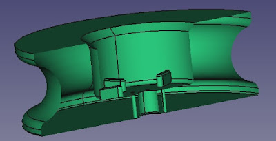
A look at what is going on with these "glue on core only" assembly jobs:


Yeah that seems like it would make for awesome flywheeler internal ballistics, right...

It's not like this is new knowledge at all - dart tips that aren't glued to the end face to the foam have been known to cause flywheel blasters issues ever since the era of clone Streamlines and later, ACC darts.

It's just that up to this point, it has been assumed that this isn't a major problem for tips like the waffle, the accutip, the Sureshot, the Mengun, the brick/stagger tip, and so on. They still shoot fine, right. Right.

Mostly.

Well, I was chasing 2 issues. One, at the last game I played, I had a lot of ...questionable ballistics. My full length 9.0 rigs with these offending darts incidentally did about the same on range, drop and group size when fired side by side with other flywheelers at the event using the ammo their owners fed them (Banned Blasters flywheels Gryphon, one of those beta Gavinfuzzy SBF things, full length and short FDL3 builds, etc.) but still I could tell something was Not Right and they were just shooting kinda dirty and under the weather. There wasn't a chrono onsite so I couldn't ascertain what velocity was doing under site conditions, but I was spamming at people I should have picked right off. I chalked it up to imagination, or me being mad rusty after being on hiatus for a while, or that using black darts was a terrible idea that makes it harder to see your "tracers" fly and compensate when there is any wind, but doubt remained that something untoward was going on with my setup that day.

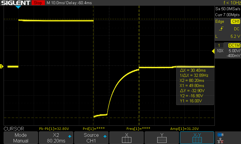
Two, I was trying to use these pictured batch of black foam accutip darts in some chrono sessions with T19s for a project to be discussed later, and holy crap, they DO shoot like garbage and I was not imagining things. I had strings of dud shots down in the 140s, 150s, 160s from a 9.0 cage at 25k, stuff going sideways as soon as it cleared the muzzle, and ...well, my other 2 batches of waffles and accus misbehaved the same way. Swapped blasters: Same results. What on earth is going on???

Granted, the weather during all of the above was typically 90-96 degrees Fahrenheit, near 100% humidity, and that may well be WHY this started manifesting so severely after having eluded notice for so long (part of it is also that I never actually used non-reglued bulks as a chrono or ballistic testing standard because of the decap rate expected of such darts, which was a problem I was willing to accept for the cost), but this brought to light the magnitude of this problem.


That problem.

In the end, I got my data. I disassembled the problem darts, reglued them with Plumber's Goop (Amazing Goop, whatever Goop, all the same stuff, all a great dart adhesive and similar to what the first rate vendors use), let cure, and what do you know, they shoot lasers. Velocity was back up to nominal (hanging just under 190fps on an old 9.5 gun), the velocity spread was somewhere around +/-3 fps typical - might note, with reused darts too - and there was zero doubt in my mind about how those two 9.0 blasters were running anymore once I fed them some.

Conclusion


It's not just decaps that are at stake with dodgy assembly of darts, as everyone (including me) tended to think for years. It does, or at least can with the wrong batch of darts and conditions, seriously screw with the internal ballistics of flywheel blasters whether or not any tips come off at all.

The old wisdom from the "ACCurate" dart + Rapidstrike = squib/fail observations (where simply regluing the dart removes the problem, as if by magic) still holds. It holds even for full-caliber tips, like waffles and accutips. The tip needs to have a moment connection to the foam.

That is what it is - A moment connection. You can tell instantly by just touching/feeling the reglued dart - bonding that region makes the whole front of the dart much sturdier and stiffer. Glue on just the core is not that. The compound used to make rubber tips is very elastic, and the tip is basically held on by a rubberband and can flap about loosely, for blasting purposes. Likely, the tip is tilting due to an imbalance of initial friction forces for whatever unavoidable reason, being forced through the rest of the contact zone at an angle, and then getting wedged into the control bore wall incurring severe losses - but I would need high speed video equipment to catch the failure mechanism in the act.

Ramifications


Well, for one thing, bulk darts that haven't been reglued are never getting fielded by me again. It's at this point that I realize that in a lot of everyday game scenarios where I choose cheap darts to burn (for not wanting to use any of my reglued, handpicked or expensive good stuff) I have likely been at least intermittently down on performance, in addition to just chopping frequently.

For another, this all with realizing these to be basically unfit for purpose has exposed the fact that designing flywheel systems around not "instakilling" non-reglued bulk darts of this sort, the kind with a tiny smidge of superglue on just the core ...is a legacy idea that is very much no longer relevant to modern NIC. "Why not more crush?" Well, why not more crush? I think I'll experiment with more crush.

Are bulk darts obsolete? I wouldn't say so, at all. It would be different if the same products were available with better glue, but Prime Time's two Sureshot tips are not (pending testing/data on the green tip/red foam dart, that I have coming to do just that) quite heavy enough to be a true range-maintaining replacement for waffle and accustrike. The blue tip Sureshot (1.0g) is definitely just not heavy enough and too droppy for outdoor work. Same, incidentally, with most of the sub-caliber springer tips, which are also expensive and have given me some questionable results concerning inaccuracy of reused darts, high foam wear rate on flywheel and other factors.

Wednesday, June 8, 2022

Some motor controllers and other electronics WIPs.

Just a bit of what has been going on lately. First of all, the implementation of that fast decay solenoid drive topology in my usual style of blaster manager board:


These are being called E-Core. They have pretty much the same featureset and I/O as S-Core, with the addition of bus voltage sensing vis the ADC and 2 extra (PCINT) tach channels for a total of 4, something that will be standard going forward to provide the best 2 stage cage support with speed monitoring on all wheels.

The powerstage is driven by a LM5109 (or any other basic IR2101 compatible driver). Obviously as from the post on the topology this is not a halfbridge, both switches need to be on at once, and a driver with shoot-through protection won't work. There is an AP3012 boost converter fed from the 5V rail for the gate drive rail in the usual arrangement I use (overkill, I know).

Now for something different (non-blaster):


This is a SimonK controller using singly parallel LFPAK88 FETs in the "sandwich" layout, with generous copper area (to say the least). Board dimensions are 72x100mm.

This is aiming to run a 190kv 6374 motor on a scooter on 6-7S using Nexperia PSMNR55-40SSH (go look that device up, it's insane, by the way; half a milliohm typical at only ~190nC of gate charge). Drivers are Infineon 2EDL23 series. MP2459 (55V rated) for the logic power and again an AP3012 off that for gate drive at ~14V. Since this is going on a vehicle, the power supply overkill with the input sag eliminator and "buck then boost" approach to derive the gate drive rail for maximum voltage headroom are probably justified.

It's experimental I might add, but I'm pretty sure I will have pulled this application off with only six devices; the thermal numbers work out okay-ish even for unipolar PWM (with diode conduction) and some sustained partial throttle that may be seen in use. The low side device that may have diode conduction in the usual arrangement is actually positioned with the drain tab more directly over the double-sided phase node pour where all the vias are, and that will be further heatsunk by a 10AWG phase wire, so... Oh, and I've got a a pair of very heavy solid copper heatsinks made for NVMe drives (surprisingly cheap!) that are planned to be clamped directly onto the top of each rail of FETs with thermal compound. They are not best heatsunk that way but the case is pretty thin compared to usual, and it does help.

And here's another board along the same lines. This one's a bit smaller, designed specifically as a "high" voltage platform for 80-150V class FETs and takes D2PAK-7 devices and 12.5mm caps.

Pretty similar idea; no worrying about the size of the board here, priorities are on robustness/good cooling for SMD FETs as this one is meant mainly to run a brushless string trimmer I found in the trash with a good motor, no battery and a questionable inverter, and other similar sorts of projects involving ~12S. High voltage power tool fixes/conversions, etc. Driver is a FAN7888 as I have a handful of them from a long time ago I never used for blasterscale projects. LTC3638 (140V buck) and a LDO for gate drive and logic power.


Back onto blaster stuff, I have been wanting to dump the "ESC" form factor/paradigm since forever, so this is what the ACE-NX is evolving into:

This for reference is only 22mm wide (quite a bit narrower than the NX Inline aka the traditional ESC styled version you might know that the T19 uses and so forth) and about 76 long, so a nice long skinny form factor, just the ticket to either conceal these in apt places within predominantly long, skinny blasters, or to have a nice neat farm of them somewhere when you have a multistage or otherwise a bunch of motors that need driving.

It uses LFPAK56 FETs, the same Infineon 6EDL04 driver in TSSOP28 from the original NX, and due to area/complexity reasons, the same LDO logic power/AP3012 gate drive supply arrangement. DC link caps are 4 10mm units which offers a sound improvement in everything (thermals, ESR, etc.) over one giant capacitor and allows building these with a low total height using i.e. 220 or 330uF parts from Rubycon and others. In addition there are 3 1206 MLCCs. Having a few good snappy ceramics in there is something I am doing in all these new designs.

Oh, by the way, no, the cap footprints do not overlap the FETs in this or any other boards here. Those FET footprints are expanded by a LOT because it makes them easier to solder.

In addition to being a much more electrically optimal layout for the DC bus and so forth these should be thermally quite a bit better than the inline boards. Not that the inline boards have had issues. The bottleneck is probably (as in the inline boards) the phase nodes which have the drain of one of the FETs on them, but then again see the remark about phase wires. Phase wires are not appreciated often as heatsinks but if you work with this stuff or ever see a running controller thermally imaged you quickly realize that as long as they are oversized for ampacity they are a heatsink, not a source, and help get FET heat out of the thing. Hence a move to oversizing the phase pigtails on boards, such as 16AWG.

Not shown (forgot image): a LFPAK88 "Max" version of the same board (i.e. ACE-NX.88m) - which is 34x80mm and has the extra stuff like switchmode logic power, the input filter and so forth and accepts 5 caps. I don't know WHAT would ever reasonably be done in a blaster that this one won't be able to run... And also not shown, the ATmega328-based throttle interface board for the scooter project and the trimmer project and anything similar where you want Hall effect/potentiometer input to PWM throttle, battery low voltage cutoff, battery gauge LEDs, any datalogging or control loops you care for, etc. which is mostly just a MCU and a bunch of passives so little to write home about.

And this is in the ACE-NX Max when I was working things out. Now that's the best you can hope for, for nearly all of a MCU/gate driver lane (what happens when you created the board definition specifically for that driver, lol). Internal pulldowns in the driver.

Actually that's maybe noteworthy. I have really liked Infineon drivers so far. Internal pulldowns on logic inputs, internal pulldown on gates when the chip is not powered (see 2EDL23 series datasheet), internal bootstrap diodes with built-in ballasting resistance. That's quite a few annoying passives and bits deleted from a board. And robust input filtering, with short pulse rejection (read up on that issue with traditional HVIC gate drivers if you design this stuff and want to lose a bit of sleep).

Wednesday, November 10, 2021

Solenoid power stage topology followup - Preliminary decay mode investigation.

This is the "partial fullbridge" topology (2 mosfets and 2 diodes) from the previous post roughly prototyped.


And the overall setup. The test solenoid is a Takaha CH12840062. This in stock form is a total slug and definitely not the greatest choice of blaster bolt drive noid, incidentally.

I just used random crap I had around - some IRLR7843s for the switching devices, 1N5819 diodes, and for the highside drive I used a discrete bootstrap driver as in traditional ESCs. A tiny bit of code on a mega328 to drive the power stage, take a switch input and spit out a drive waveform (in this case generic 50ms on/50ms off).


Anyway, so this is what the voltage across the winding is doing with the regenerative fast decay case:

(10ms/div, 5V/div)

Exactly what we expected - it flies up to the DC bus level (mostly charged 4 cell pack) for the 50ms on-time, then flies down and is caught to negative (DC bus + 2 schottky diode drops).

Note that the total current decay time is not really the 30.4ms I had the cursors on. That is the duration of the negative voltage transient on the winding - but current is only really flowing when the voltage is below negative DC bus i.e. during the flattish, ~10ms long period right after switch-off. The exponential rampy part at the end happens after the diodes have mostly stopped conducting entirely and the voltage decays back down (up) through parasitics. The small but existent step up at ~30ms after switch-off is an artifact of the power stage switching to slow decay mode by the low-side fet being turned on at 30ms after switch-off (random value I picked). With a bootstrap high side driver in this arrangement the low side must be on at some point whenever otherwise unimportant (like this) during the off-time to present a path for the high side bootstrap capacitance to charge.

Now what happens if we run that again, but in SLOW decay mode - exactly equivalent to the typical circuit with a flyback diode across the winding? (20ms/div this time as I had to back off to see all of the decay time!)


Here I did that by keeping the low side fet permanently on, so we're doing high-side switching and the flyback diode is the one coming from ground up to the switch node. I of course did that because the high side driver is bootstrap and we can't keep the high side on as the cap will slowly discharge through parasitics.

What we're expecting here is DC bus level for the on-time and then one diode drop below ground (small, because this is a schottky) whilever winding current is still flowing through the flyback diode. And that's exactly what we get.

Note how long that negative period lasts! Here's that a bit closer (500mV/div):


That weird low frequency ringing in the setup that went down to -2V on the switch node wants our attention, but here the ~120ms of actual decay time is the shocking matter...

And yes, the solenoid immediately felt PROFOUNDLY more sluggish to release during these shots.

Now what happens far as trying to cycle quickly?

I have had this noid cycling (unloaded) very reliably at 10Hz with the 50/50ms timing using the regenerative fast decay setup:


No problem. Now, this is the same noid, the same timing parameters, the same otherwise hardware, the same battery powering the setup at the same voltage (immediately swapped between modes)... the only variable here is the decay mode which is now slow (aka, standard flyback diode configuration).

Okay; so I would say there might indeed be an issue here!

Now, this noid is a 6.2 ohm coil that is probably more turns and more inductance than typical sub-3 ohm blaster bolt solenoids and is also a bit lacking on return spring hence is making a more dramatic example of this than usual, but clearly something major is afoot here with this decay mode thing and the notion that a simple flyback diode is a hindrance to fast-cycling solenoid actuators. This will be very interesting to apply this topology to more known-quantities like the FTW Hyperdrive and quantify the timing margins gained over the flyback diode approach.

Sunday, November 7, 2021

Thoughts on solenoid power stage topologies

 ...Specifically, in the context of bolt actuators.

In the nerf hobby up to this point, we have generally had exactly one answer to this question - the classic single-ended arrangement with an antiparallel diode (same as when you want to switch a DC motor on and off, or do one-quadrant variable speed drive of one). "Don't forget the flyback diode!" Here's the sort of thing I'm talking about:


Where signal, rail and output names are obvious. It's usually low-side switching like this, because we like N-channel power devices, and we like relatively low level, ground-referenced gate drive voltages.

Or sometimes, as in Narfduino boards and other multipurpose power stages, it's a halfbridge. Same difference - the antiparallel diode in the above is just taking the place of the missing high-side device, whose copackaged diode would otherwise be serving this purpose (providing a path for the winding current to continue flowing at switch-off). We could also be doing synchronous rectification with a halfbridge, also fundamentally the same thing minus the diode loss.

--Is this a new concern? --But isn't driving solenoids just like driving DC motors? (Etc.)

In short no. With motors - even DC ones - the winding itself is not a DC device, it subject to an alternating current at some fundamental (commutation) frequency, and so by design for a motor that is going to turn at some given speed and thus have each winding current ramping up and down at some dozens to thousands of Hz anyway, there cannot then be any significant concern with current decay time at switch-off having any major influence on how the system responds.

By contrast - many solenoids are comparatively large inductances for which ramping the current in the coil up and down might be significant compared to the cycle time. The current slew rate of a solenoid is directly the force slew rate, and in many applications the time required for current to ramp down in a coil simply shorted by a forward-biased diode or synchronous rectifying switch adds electromagnetic inertia associated with the stored energy in the inductance to the system's mechanical inertia, and slows down, for instance, the opening of relay contacts, the closing of an injector or valve, or so forth - and in those cases, limits the system's frequency response significantly (and for relays, accelerates contact wear due to arcing during the slowed opening). For a blaster bolt actuator, this is an open question whether it really matters "that much", which comes down to whether the comparatively massive solenoid plungers involved might be a dominant constraint. But of course it is highly desired to end forward force as abruptly as possible, so as to get the bolt back open to pick up the next round as quickly as possible (hence the focus on return springs and their selection). So, slow decay on a noid might be questioned regardless as a low hanging fruit.

The most likely candidates

Tons of power stage topologies have been created as dedicated coil drivers. Some of them are downright elaborate (mainly to provide both fast decay for switch-off and slow decay while doing PWM control for continuous conduction and low losses), but two stand out to look at here which are appropriate and not over the top of what would fit or be afforded in a blaster.

This is a common one.

The basic idea is to insert a bias voltage in the flyback path so that the inductor has a load to push against to absorb the energy quicker than just the coil resistance and assorted other parasitics. A TVS diode is often used for that purpose as it is designed to absorb abusive power pulses and have a predictable clamping voltage available in various increments. A MOV has been put in there similarly. Even a string of regular diodes in series to build up a voltage drop could be used, as could a resistor as long as the voltage at the output node under peak flyback current is considered, though that wouldn't be optimally effective.

With both the regular rectifier diode and the TVS, the latter can obviously be unidirectional rather than the bidirectional shown. Also, having both means the TVS breakdown voltage does not need to be higher than the supply.

This would be simplified version for when the TVS breakdown voltage is always higher than the supply.


Now, this idea comes with a downside that is a non-problem for everyday relay drivers but might be a major design problem for blaster bolt actuation. Blaster bolt drive solenoids are downright monsters as they go. They might be running peak currents of 20 amps in some setups. Accordingly they are going to not only have that much flyback current to be clamped (and now clamped by a device which has to take that with a large voltage across it), but the inductive energy to be disposed of on each cycle will be large - and when a dissipative device is used in the flyback path to speed up the decay, that device now relocates to itself some power dissipation that would be mostly in the (thermally massive) winding with the usual antiparallel diode circuit. This is perhaps not desirable in a compact bit of blaster management kit.

So here's another strategy seen on occasion:

This might look like a funny halfbridge with some extra diodes at first, but it's not. Let's rearrange it a bit:

...And now it's apparent what's going on - this is analogous to a fullbridge in the same way that the traditional single-ender with flyback diode is analogous to a halfbridge in that active devices which are not needed in forward mode are replaced with their vestigial diodes.

The advantages might be clear just seeing it (or not) - one, the inductance now sees the DC bus as a bias voltage to push current into when decaying, so the current can ramp down a lot faster. Two, since that current burst is pumped into the DC bus on each switch-off and no intentional dissipative element is used, some of the energy is recovered and the overall losses reduced rather than simply moved around.

Disadvantages are that we just multiplied output devices and diodes by 2 and required a high-side gate driver - but that might be a tolerable overhead. Also, compared to some of the exotic ideas involving high auxiliary voltage rails, DC-DC converters, storage caps, etc. and the TVS-based ones, the voltage is limited to DC bus, so the slew rate performance couldn't be as high in theory, but in practice I doubt we would be seeing noid drivers designed with 100V fets and ~40V flyback clamping anyway, instead closer to the 14-20V DC bus in a light blaster configuration, so it seems promising.

Methods I didn't address

Active clamping, because modern mosfets should not be operated in the linear region. This is mostly confined to specialized monolithic devices meant to drive coil loads about an order of magnitude less in required current than a blaster feeding noid.

Avalanche breakdown of mosfets as an intended way to dump the energy, because I don't care if Nexperia says it's OK, considering intentionally doing that makes me ill. And because there is probably too much stored energy for most fets thus rated anyway.

Alternative arrangements of the TVS version that don't really achieve anything other than expanding loops (etc.) such as having the load hung off the bus and the TVS from the low-side switch drain to ground.

Anything to do with PWMing or current controlling a noid. That stuff is tangential (though has specific requirements of power stage design) but mostly is just irrelevant to a blaster because the entire purpose of doing so is to account for the fact that a fully traveled noid produces the maximum force and a load requires less force to hold than accelerate. In a blaster there is no reason for the bolt to hold forward at all, thus for current to continue at all after the solenoid has fully traveled. Closed-loop control of a noid on that end amounts to "hitting the end of travel shuts off the driver immediately" no matter the implementation.

Anyway

Off to buy some solenoids and test some stuff. I finally have a scope of my own so next time I post about this I'll have scope shots of how bad the decay issue really is or isn't with this specific sort of noid.

Note

Don't read anything into the fet or diode part numbers. That's just a LFPAK mosfet and a SMA schottky that were close by in EDA. That fet is probably more than fine as long as 30V is sufficient blocking voltage for the bus (about half that is 4S), that's a 1.4mohm device from my older inverters for 22xx series flywheel motors. The diode being rated for only 3A average rectified (though adequate pulse rating) might indeed need to be something bigger depending on what the actual inductance of the 35mm and Hyperdrive are.

Further reading

https://e2e.ti.com/blogs_/b/industrial_strength/posts/tips-for-solenoid-driving

https://www.eevblog.com/forum/projects/solenoid-driver-design/

https://electronics.stackexchange.com/questions/438644/solenoid-fastest-possible-release-for-how-long-should-reversed-polarity-be-app/438657

https://www.nexperia.com/applications/interactive-app-notes/IAN50003_driving-automotive-solenoids.html

https://www.maximintegrated.com/en/design/technical-documents/app-notes/6/6307.html

Saturday, June 19, 2021

Field Report: Mystery Machine and Orb Weaver

Hop ups

The hop ups work well. I can adjust them in the field from no effect to curve straight into the sky. 


Accuracy seems about on par with rival blasters using rubber flap hop up. 


Considering how simple this design is, seems like a winner.


Mystery Machine

This performed admirably for most of the day.... until the end when it mysteriously stopped working.  What happened? 

Turned out the nub detention mechanism broke.

./documentation_images/physical_build/used_images/old_broken_catch.jpg 

This is after cleaning up the snapped off plastic and co.

Turned I designed it, I did the nub retention platform first, followed by the  rival round feed path. I stupidly didn't notice the feed path cut into the nub retention platform, leaving just 1-2 mm of PETG to withstand the impact of repeatedly slamming a mag in. 

Oh well.


Time for version 1.1.


A M3 screw actually works REALLY well as a catch for the nub. Better than the original plastic design even. 

./documentation_images/physical_build/used_images/new_catch.jpg 

Hard to imagine that breaking from any number of magazine inserts. 


 V1.1 also changes the magazine catch to work with worker 15 round mags.


Orb Weaver 


I used this for the UF HvZ game, and several NOMAD PvP games.


Overall, it's performed admirably, with just a handful of nits.


  • During a PVP game with targets in trees, I aimed at some odd 40-60* angle up, and unsurprisingly, quickly stopped feeding. 
  • During a run in HvZ, the lid got bumped hard enough to spill the balls. Maybe two magnets are needed? Then again, was a pretty hard run. 
  • There's been a handful of firing twice incidents.
  • It is heavy at 6 ib. A significantly less dense (and of course, weaker) print could be worth a shot. 
  • Optic mounting is awkward, but I knew that going in. 

And that's about it.


I'm pretty happy with it, and plan on continuing to run it at HvZ events.  


Surprisingly didn't wind up with very many pictures of this game, if any one has some please do let me know!


Tuesday, March 9, 2021

T19 Heavy - 20x95mm MEGA; Mega-Con flywheel system

Ever since the modern (20mm) MEGA caliber and the Centurion was a thing, I have been wanting to build something reliable and magfed to run them full auto. This has only intensified with the advent of special rules for MEGA hits such as defeating shields/armor, killing special zombies, causing double damage, and counting as more points for DTC-like gametypes.

I never ended up doing what I should have back in the dark ages (jam a Zeus cage and a RS pusher box into a hacked up Centurion receiver), so the intent to eventually do a 20mm project followed me all the way to the T19 era, and now I finally got a round tuit to spare and did it.

Hence:


Of course, this starts with a flywheel system. As a starting point for the profile geometry, I loosely scaled up the .50 cal Hy-Con including the 0.56-ish centerline area ratio, yielding 22mm control bore, 22mm rim width, and 15mm gap. I then designed a 67mm centerdistance (jumbo format is probably the best descriptor) system around that, yielding what is more literally a scaled-up Hy-Con than not.

For motors at dev stage, I used Racerstar BR2207S, as I had some 1600kv ones on hand already.


This might drive home the scale of this system. .50 cal Gamma cage looks downright small next to it.


Now this needs a breech. I opted for the existing mag standard. It's easy to get caught up in This mag design has X mm of wasted length! and similar griping, and that's how we get crappy, incompatible mags. Some careful design was required to use these mags, including the rear feed ramp to deal with top round positioning issues and the 0 mm cage flange thickness in front of the mag to keep required bolt stroke to a minimum.


Design elements are all the same as other modern T19 breeches. Angle cut, flared magwell, overinsertion stop on feed lips, no fence on the front for comfort, 7mm flanges, ...

This then gets its own mag release, its own side cover set (below), and a stock T19 drivetrain stack with the exception of a slightly longer bolt.


Add in a top rail front segment and one underbarrel gap filler/finisher/hand stop doohickey to polish it off, and we get...


Filaments in this build: Yoyi translucent red PETG, CC3D bluegrey PETG, Makeshaper orange PETG, Overture white PETG.


Results


Overall excellent. I have had Hasbro mega up to mid 160s fps, and the one used Whirlwind I currently have up to 140-ish, and breakin wasn't even complete when I shot those. Also, this is really easy on ammo compared to a Zeus cage on mega --or a .50 cal T19. Reliability is so far awesome at the 12rps I have it set to max out at. It will feed and shoot just about anything and I have probably shot some of my testing darts 15 times into hard objects by now.


Now about the bad: The motors. I grabbed these because I had them and they would work for a ballistic proof of the cage. This could really use a larger, more modern motor, and also slightly higher kv than 1600, or else 5S or 6S. Spinups to high (which is 18-20k for this) speed are pretty crappy by modern standards, though not unuseful, with the 1600kv BR2207S and 4S. Also, Racerstar motors have quality issues and as usual the dynamic balance on this system is not great. I'll probably go for T-Motor F80 for an upgrade/option for this in the future.


Release


Link


Release notes duplicated here:


###############################################
# T19 MEGA (20x95mm) Initial Release 03-07-21 #
###############################################

Takes Hasbro-style 20mm mags. Mag tolerances are crap on commercial mags,
and some may need hand fitting with a file, particularly clone mags, as well
as release notch issues needing adjustment.

3 mag releases have been provided: the "stock" and -1mm (lower) straight
versions, and the "circular surface" one which is closer to what my hand fit
"stock" release ended up as after adjusting to get easy lockup and minimal play
once locked on all my mags. I recommend trying that one first. Some hand fitting
may be required regardless.

The "MegaMagDropfreeifier" part is a mod for Hasbro (style) 20mm mags which fills
in the second void/notch above the actual release notch, which often causes
trouble with snagging on the release. Print it out and glue it to *one* half of
the mag body (not both). File smooth and/or fill with a little devcon.

Top rail: Uses the T19_TopRail_NewFullLengthRearSeg.stl rear rail segment used
by the new (Gen2) .5 full length breech. Front rail is specific and included.

Bolt is different. All other drivetrain, stock, controls, etc. parts are the
same as a .5 cal T19E1.

Firmware difference is maxRPM=20000 and maxROF=700.