This is only mostly right: there is a benefit to having a diode here, albeit a small one. This diode would provide a small stability benefit, by turning what would otherwise be a runaway into a single or a small number of trailing shot(s). Planned use of such a system would be a prime example of smart-dumb engineering: smart because it solves a problem, and dumb because a well-made system damn well should not have this problem in the first place. A voltage drop in this location is suitable as a protective measure in a fully stable build which is at risk of becoming unstable. There are several ways that this could happen - degradation of parts resulting in an increased braking resistance was previously noted. The use of batteries with an unexpectedly high voltage is also a possibility. Notably, NiMH batteries may have a higher than expected voltage when hot off of the charger, depending on the charger.
Now: what if we used a resistor?
Using a resistor in place of a diode when dropping ROF is usually not a great idea. A resistor which produces a similar drop in ROF to a given set of diodes will produce a greater increase in lock time, which is undesirable. Furthermore, it is usually pretty easy to tell in advance how much of a voltage drop you want when using diodes: regardless of what motor you have, a voltage drop produced via a diode will have the same effect as if you had used a battery of a lower voltage, whereas with a resistor, the relationship between the ROF and the resistance is more complex and depends on the battery voltage and the motor used.
However, dropping ROF is not what we want to do here, and here, resistors can do something very useful which diodes cannot: they can provide protection in the event of a stalled pusher.
Let's do some back-of-the-envelope calculations to see what sort of resistance we would need here. Let's assume a freshly charged 3S LiPo pack, as this voltage (12.6 V) is the highest that we are likely to see, and an FK3240 on the pusher, because this is a fairly common pusher motor with known specs. An FK3240 draws 1.54 A when operating at maximum efficiency at 3 V, and the effects of a stationary rather than moving commutator on motor burnout are difficult to estimate, so 1.5 A serves as a conservative-ish rough estimate of how much current an FK3240 can comfortably withstand while stalled.
This suggests that the highest resistance which we might want is 8 Ohms. Realistically, we could probably get away with something lower.
What effect will this have on the speed of the automatic operation of the pusher rod? Most of the time, this will not be a concern due to the momentum of a RS's pusher box. The fact that a dead-center RS will terminate a good proportion of the time with the pusher rod nearly fully retracted should give an indication of how significant this momentum is. The worst case would be a marginal trailing shot - i.e. a shot where the pusher is left on the far side of the braking region with little momentum, and the automatic operation of the pusher rod carries the rod through an entire cycle. As the pusher motor experiences a load which is not known and which varies over the stroke, the effect of this resistance is difficult to calculate. However, it is worth noting that 8 Ohms is pretty close to what some people who use resistors to drop ROF use - see this post where Boff of the BirtNerf forums links to some 7.5 Ohm power resistors which he used in a batch of RSs.
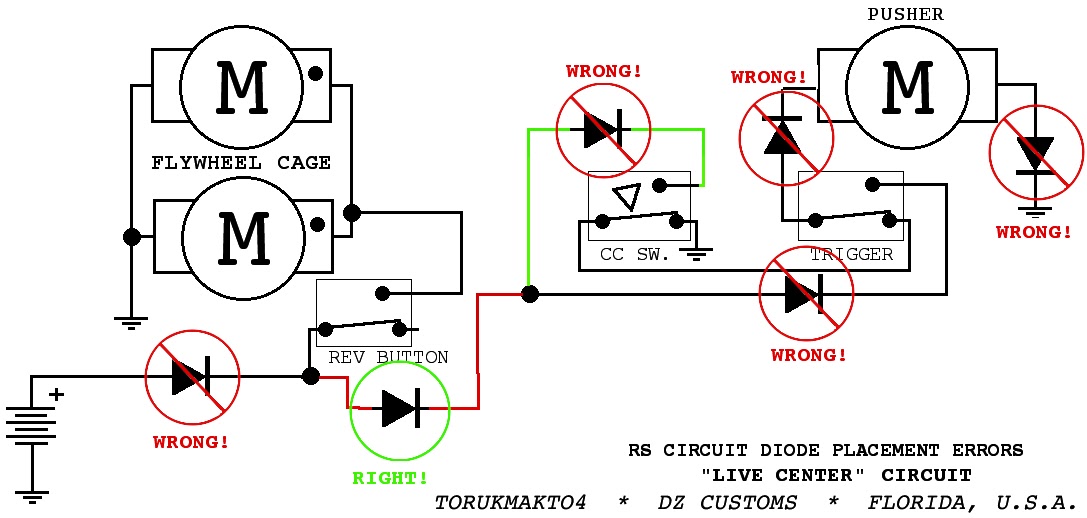
So, there you have it: the resistive-center control circuit. Start with a live-center circuit, and put an appropriately-rated resistor on the wire that runs between the battery and the cycle control switch.
Advantages:
- Predictable trigger response, as a standard live-center control circuit.
- Reliable pusher position control, as a standard live-center control circuit.
- Protection in the event of a pusher crash and any other sort of pusher jam. This protection is inherent to the circuit, and does not rely on the user to release the trigger quickly.
- Trailing shots are possible, and may be fired with a greater delay than with a standard live-center circuit.
- Safety, though less so than with a standard live-center circuit. An unattended powered blaster which suffers a mechanical failure in the cycle control switch may have its pusher operate continuously. An appropriately rated resistor should reduce the fire hazard, prevent damage to the motor, and prevent battery damage through excessive discharge rate. Battery damage through overdischarge will take considerably longer than with a standard live-center circuit.
No comments:
Post a Comment